TLC heat engine
The design of a TLC heat engine (TLC-HE) does not differ fundamentally from the well-known designs of a steam turbine.
The TLC rotor, as the rotating component (comparable to a turbine wheel), is mounted in a housing on a hollow shaft so that it can rotate.
The housing can, but does not necessarily have to, serve as a storage tank for the cold liquid working fluid.
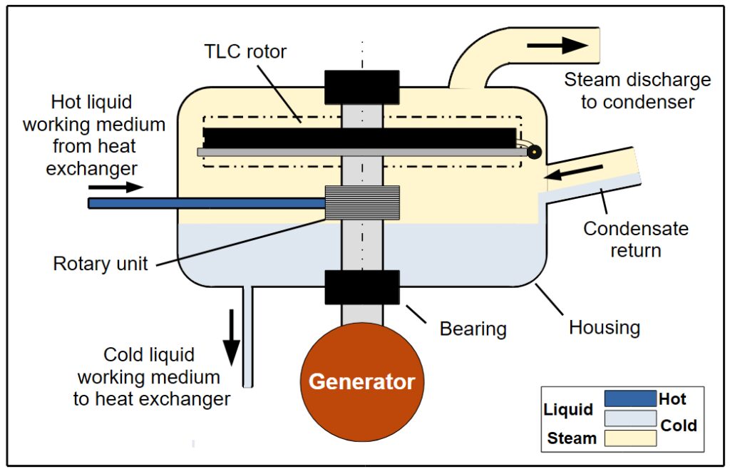
The hot liquid working fluid is supplied via a rotary feedthrough of the hollow shaft, from where the working fluid flows into the TLC rotor.
In the TLC rotor, the actual conversion of thermal energy into kinetic energy (flow energy) takes place, which, when the partially evaporated working fluid exits a nozzle, generates a force acting on the TLC rotor.
This force sets the TLC rotor in rotation and thus drives the generator.
Power increase and variable power
The flat design of a TLC rotor enables a simple power increase by operating multiple TLC rotors on a common rotation axis (figure left).
Separate working fluid feeds to the individual rotors (figure right) allows a simple stepwise power control.
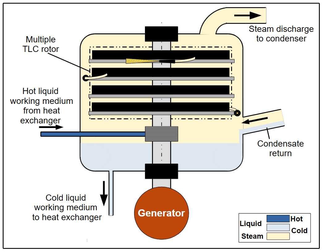
Multiple TLC rotor

Variable operation